Paradox Security Systems alarm in Home Assistant
This post details how to integrate a Paradox Security Systems alarm system into Home Assistant using an ESP32 board (i.e. without the use of an IP module), so that it’s possible to both read (alarm triggered/armed night/armed away/disarmed) and “write” (set) its state (arm night, arm away, disarm) The state of all motion and door/window sensors is also exposed.
This is a follow-up to my earlier post on doing a similar thing with an Ajax Systems alarm system.
Prerequisites
This has been implemented on an alarm system that has an SP7000 board. If you have another board, YMMV.
Components
- ESP32 board with hardware UART. I used a LILYGO T-ETH-Lite ESP32-S3 W5500 I had lying around since I wanted a wired/Ethernet connection with my router to make it as reliable as possible. WiFi should work as well.
- FTDI232 USB-to-serial board or similar to flash the ESP32 board if it doesn’t have an integrated USB-to-serial chip (most boards have) + USB cable to connect to your computer for flashing the firmware
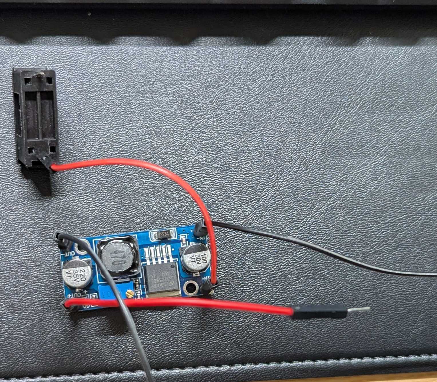
- LM2596 step-down (buck) adjustable converter to drop the alarm board’s 13V to 5V that the ESP32 board can handle at the VIN and GND pins (see Future improvements)
- 2.2 kΩ and 4.7 kΩ resistor to build a voltage divider to convert the alarm board’s UART TX 5V signal to 3.4V that the ESP32 UART RX pin can handle.
- 470 μF electrolytic capacitor + 0.1 μF ceramic capacitor to stabilize the power to the ESP32 board and handle brownouts
- 4-pin female headers (see Future improvements below) to attach the connections from the board (VCC, GND, UART TX/RX)
- Two (2) N-pin female headers for the ESP32 board (choose N based on the number of pins your ESP32 board has) This makes it possible to swap boards later if needed.
- Four (4) 1-pin female headers (see Future improvements below) for the LM2596
- Perfboard (I used one with 18x24 holes) to solder the circuit on
- Some 22 AWG flexible tinned wire for the connections in 4 colors (I used red for VCC, black for GND, yellow/white for UART TX/RX)
- Several DuPont-type (fe)male-to-(fe)male breadboard jumper wires for connecting the alarm board’s pins to the circuit as well as the alarm board’s VCC/GND pins to the LM2596 module
- 20 mm glass fuse case with breadboard pins
- 1 A(mp) glass fuse
Things to note:
- If your ESP32 board does not come with male pin headers pre-soldered (most boards don’t), you have to get your hands on some and do it yourself
- If you use an LM2596 module, make sure you first connect its input to a 13V DC source and its output to a multimeter in DC voltage mode, turning the screw until the multimeter reads 5V. If you fail to do this correctly, your ESP32 board will fry.
Tools
- DC multimeter with alligator clips and a small screwdriver to set the output voltage of LM2596
- Small pliers and wire stripper for preparing the wires
- Utility knife, pliers and ruler to cut 1-pin female headers
- Soldering iron/station
- Brass wire sponge (or similar) for cleaning the soldering iron tip
- Soldering helping hands
- Soldering fume extractor and/or good ventilation
- Heat gun for heat-shrink tubing
Consumables
- Unleaded solder wire with flux core
- Heat-shrink tubing to fix male jumper wire ends onto the LM2596 female headers
Hardware connections
A design I made using Fritzing for the LILYGO T-ETH-Lite board I used:
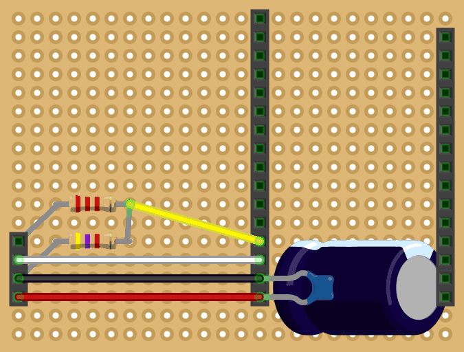
An overview of the connections (top-level pins/bullet points refer to the alarm board):
- RX
- Alarm board UART RX pin (1st from the top) connects to perfboard UART TX pin (2nd from the top)
- Perfboard UART TX pin connects to UART RX pin of ESP32 (white wire)
- TX
- Alarm board UART TX 5V pin (2nd from the top) connects to perfboard UART RX pin (1st from the top)
- Perfboard UART RX pin connects to first leg of 2.2 kΩ resistor
- Second leg of 2.2 kΩ resistor connects to UART RX pin of ESP32 (yellow wire)
- First leg of 4.7 kΩ resistor connects to perfboard GND pin (3rd from the top)
- Second leg of 4.7 kΩ resistor connects to second leg of 2.2 kΩ resistor
- GND
- Alarm board GND pin (3rd from the top) connects to LM2596 IN-
- LM2596 OUT- connects to perfboard GND pin (3rd from the top)
- Perfboard GND pin connects to
- 470 μF cap first leg
- 0.1 μF cap first leg
- ESP32 GND pin
- VCC
- Alarm board VCC pin (4th from the top) connects to first glass fuse pin
- Second glass fuse pin connects to LM2596 IN+
- LM2596 OUT+ connects to perfboard VIN pin (4th from the top)
- Perfboard VIN connects to
- 470 μF cap second leg
- 0.1 μF cap second leg
- ESP32 VIN pin (5V)
Note that even though we use a voltage divider to bring down the 5V of the alarm board TX pin to 3.4V for the ESP32 RX pin, we don’t boost the 3.3V of the ESP32 TX pin up to 5V for the alarm board RX pin since the alarm board is able to pick up the 3.3V signal just fine.
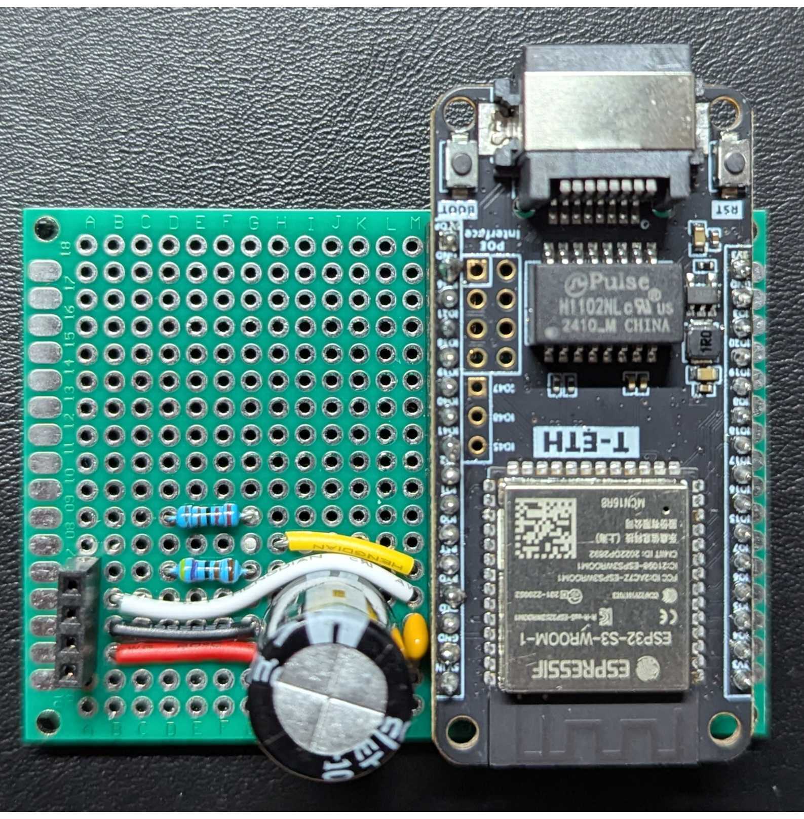
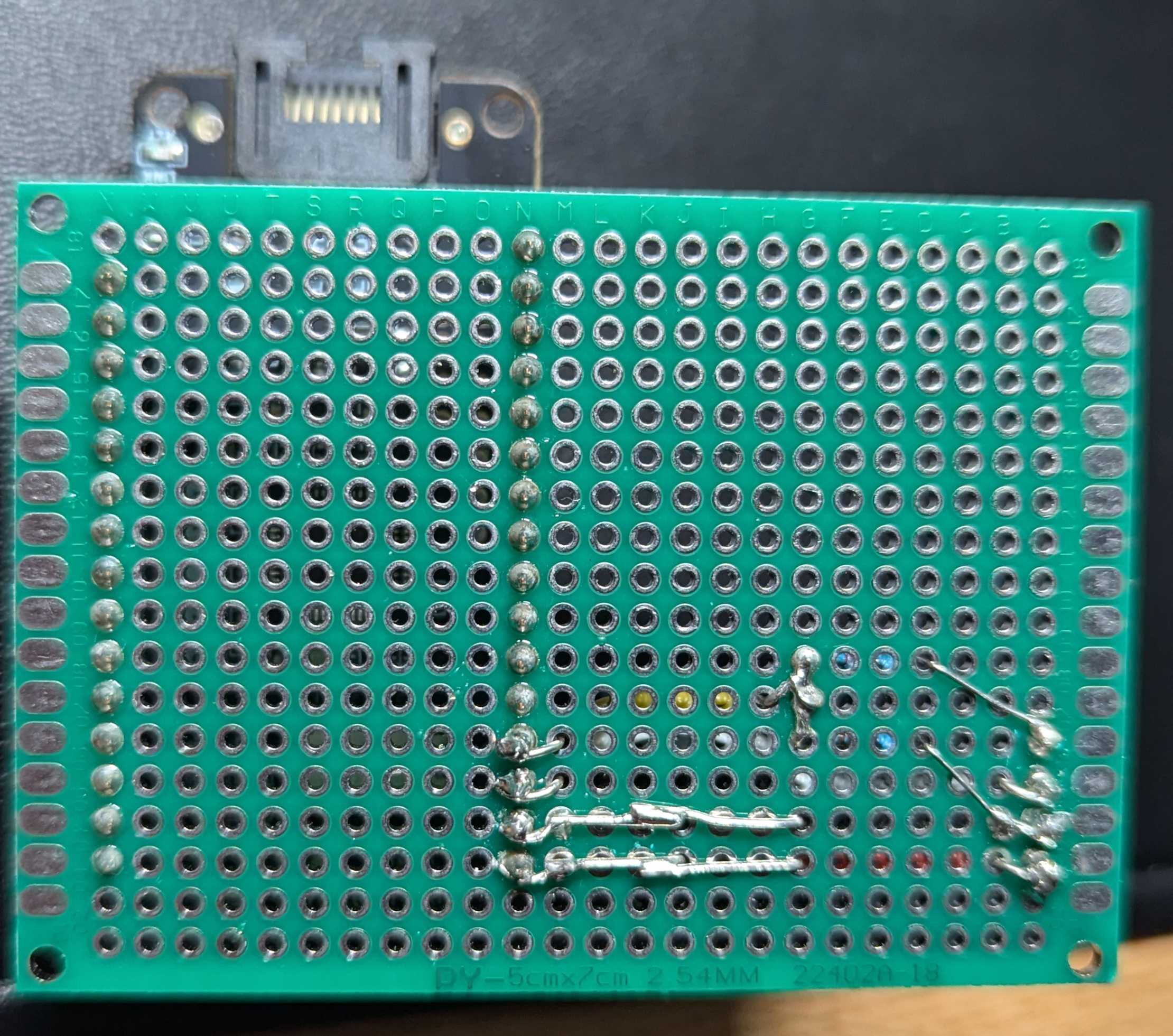
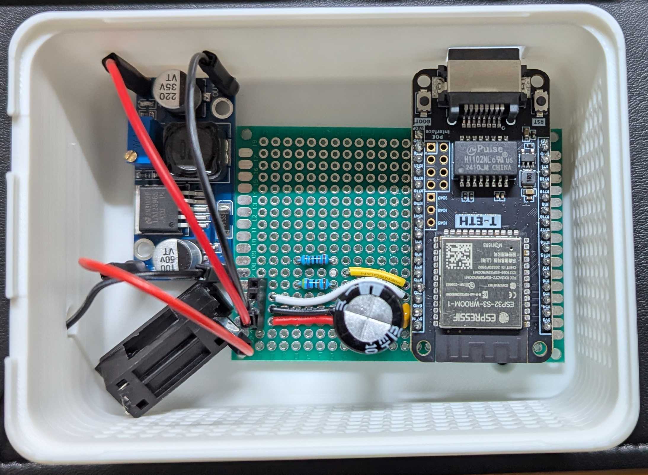
The end result:
ESPHome firmware
Note: The following code is for the LILYGO-T-ETH-Lite that has an Ethernet/LAN adapter. You’ll want to replace esp32/board with your ESP32 board type, the ethernet block with wifi and set the correct uart TX/RX GPIO pins.
Create paradox-alarm-bridge.yml in your editor and add the following:
esphome:
  name: paradox-alarm-bridge

esp32:
  board: esp32-s3-devkitc-1 # Change to your board type
  framework:
    type: arduino

api:

ota:
  - platform: esphome

ethernet: # Replace with wifi if your board doesn't have Ethernet
  type: W5500
  clk_pin: GPIO10        # SCLK
  mosi_pin: GPIO12       # MOSI
  miso_pin: GPIO11       # MISO
  cs_pin: GPIO9          # CS
  interrupt_pin: GPIO13  # INT
  reset_pin: GPIO14      # RST

logger:
  baud_rate: 0

external_components:
  - source: github://oxan/esphome-stream-server

uart:
  - id: paradox_uart
    tx_pin: GPIO43 # Set to your board's UART TX pin
    rx_pin: GPIO44 # Set to your board's UART RX pin
    baud_rate: 9600

stream_server:
  uart_id: paradox_uart
  port: 10000 # Port Home Assistant will connect to

binary_sensor:
  - platform: stream_server
    connected:
      name: Connected
If your ESP32 board lacks an integrated USB-to-serial chip (like the LILYGO T-ETH-Lite), use the FTDI232 (set to 5V) to connect the board to your computer. Connections:
- FTDI TX to ESP RX
- FTDI RX to ESP TX
- FTDI VCC to ESP 5V VIN
- FTDI GND to ESP GND
For the LILYGO-T-ETH-Lite, press and hold BOOT, press RESET, release BOOT to enter flash mode.
Build the firmware and flash it: esphome run paradox-alarm-bridge.yml --device /dev/ttyUSB0
Alarm board attachment
Connect the final circuit to the alarm board using the jumper wires. The serial port on the SP7000 board is at top-right corner. The order of pins, top-to-bottom, are:
- RX (to ESP32 TX)
- TX (to ESP32 RX)
- GND
- VCC (13V)
Home Assistant setup
- Install MQTT integration
- Add PAI repository: https://github.com/ParadoxAlarmInterface/hassio-repository
- Install PAI add-on (now known as “app”)
- Install Mosquito MQTT broker add-on and add a new login
- Username:
pai - Password: some password (write it down)
- Username:
- Go to PAI add-on page
- Turn on Start on boot
- Turn on Watchdog
- Click on the Configuration tab
- Click on the 3 dots icon on the right and select
Edit in YAMLand update as follows:
CONNECTION_TYPE: IP
IP_CONNECTION_HOST: 192.168.1.100 # IP address of your ESP32 board. Ensure static IP or persistent DHCP lease.
IP_CONNECTION_PORT: 10000 # Port of the ESP32 board HA will connect to
IP_CONNECTION_PASSWORD: 'paradox' # Factory default
IP_CONNECTION_BARE: true
MQTT_USERNAME: pai
MQTT_PASSWORD: password # Replace with your password- Start Mosquito MQTT broker add-on
- Start PAI add-on
- You should see the new alarm device created under the MQTT integration
Troubleshooting
- Connect the ESP32 to the alarm board, find out its IP and
telnetto it at port 10000. Move around the house and/or open doors/windows. You should see some relevant output from the sensor logs. - Try swapping the RX/TX jumper wires on the alarm board
Future improvements
- Use a Waveshare mini buck converter instead of the LM2596
- Use male, instead of female, pin headers on the LM2596 and the perfboard. This reduces the height of the connection since a female jumper wire end connected to a male pin header has half the height of a male jumper wire end connected to a female pin header.
- Design a more compact 3D printed enclosure (the one on the photo is a parametric design)
Sources
- https://github.com/ParadoxAlarmInterface/pai/wiki/Home-Assistant
- https://github.com/ParadoxAlarmInterface/pai/wiki/Connection-methods#serial-over-ip-esp32
- https://geriaune.pro/howto/2023/06/28/paradox-alarm-system-and-home-assistant-with-esp8266-esp32-without-ip150/
- https://community.home-assistant.io/t/paradox-sp6000-integration-without-ip150/218505